

|
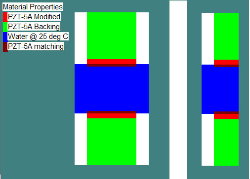
Wave2000 Plus/Wave3000 Plus for Ultrasound Transducer Design: Tutorial I (Tutorial II) In this Tutorial, examples of how to use Wave2000 Plus to simulate 2D piezoelectric transducers are presented. Wave3000 Plus simulates similar models except in full 3D (such 3D models/Wave3000 Plus models are not shown in this tutorial). A typical model used in this tutorial is shown in the following figures. For your convenience, all models of Wave2000 Plus discussed in this Tutorial can be downloaded by clicking here to download Tutorial I model files. After downloading, unzip the downloaded file and copy the model files into the data folder of Wave2000 Plus. If you don't have a working version of Wave2000 Plus on your PC, a free evaluation license for Wave2000 Plus can be used to run all these models. For information of the free evaluation license for Wave2000 Plus, please click the "Download" tab above. Tips to run Wave2000 Plus models are provided at the end of this tutorial. For readers unfamiliar with Wave2000 or Wave2000 Plus, please read Quick Start Tutorial in the help file included in Wave2000 or Wave2000 Plus. . In all of Tutorial I models, there are two identical piezoelectric transducers working in thru-transmission mode. The one at the top is the source; the one at the bottom is the receiver. Water fills the space between the two transducers. The transducers have three components: a piezoelectric layer (2 mm thick x 20 mm wide) made of PZT-5A, a backing layer (20 mm thick x 20 mm wide), and a matching layer (1 mm thick x 20 mm wide). The backing layer was made of a material that has about the same longitudinal acoustic impedance of the piezoelectric layer but has high damping coefficients. The matching layer is made of material with longitudinal acoustic impedance between water and the piezoelectric layer to improve the coupling efficiency and to modify the shape of the transmitted ultrasound waveform as well as of the received electric (voltage) signal. In the models, it is assumed there is perfect bonding between the three (i.e., backing to piezoelectric element, and piezoelectric element to matching material) layers. It is also assumed that the three layers are bonded to a rigid shell, i.e., there are no displacements on both the left and right side of the transducers. As noted, Wave2000 Plus is used to simulate the models. Since plane strain is assumed in Wave2000 Plus, the geometry of simulated transducers has a dimension perpendicular to the screen (depth) much bigger than both its height and width. Practically, if the depth is about 5 times or more than the width and height, the model will provide reasonably close approximation. Note that due to the symmetry of the geometry and boundary conditions, only half of the model needs to be simulated by applying a no horizontal displacement boundary condition along the center line (this "half-model" is shown on the right side in the above figure). This use of symmetry allows 1/2 memory and 1/2 computation time, as compared to the full model. (For a Wave3000 Plus 3D case with symmetry in two directions, a memory and computation savings of over 70 percent can be realized.) The snapshots of the simulation are captured in the following figure (for display purposes, the image has been rotated 90 degrees counterclockwise):
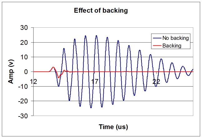
It can be seen the wave generated by the source piezoelectric layer propagates through the matching, water and the matching layer of the receiver, and then is received by the receiver piezoelectric layer. In the above shown example, the input signal is a 1 volt pulse with duration 0.1 us. The receiver output is recorded by Wave2000 Plus with a 60 dB gain. Since Wave2000 Plus assumes a linear system, increasing source input signal and reducing the receiver gain proportionally will provide the same results. The effect of backing, matching layer and input pulse width on the shape of the received electric signal are demonstrated using the Wave2000 Plus models. Note that the received electric signals in the examples are all obtained assuming open circuit measurements. It is also possible to make current measurements using short circuit conditions. Effect of Backing: Here, the models with backing and without backing are studied. As is well known, the backing material has a great influence on the damping characteristics of a transducer. Using a backing material with impedance close to that of the active element but with relatively high levels of attenuation will produce highly effective damping. A transducer with effective backing will therefore have a wider bandwidth (shorter temporal span). The backing layer was made of material with about the same longitudinal acoustic impedance of the piezoelectric layer and high attenuation: d(aplha)/df=15 dB/cm/MHz. The material properties of the backing (or of any material in the model) can be changed by using the menu command Wave->Material Property, and then setting the material parameters. To demonstrate the effect of backing layer, models without backing layer (i.e., the backing space is filled with dry air) and with the damping material backing are simulated. The receiver outputs for both models are plotted in the following figure:
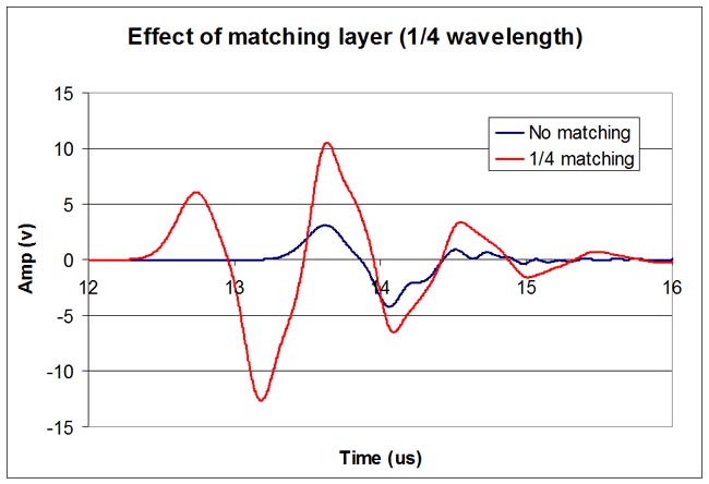
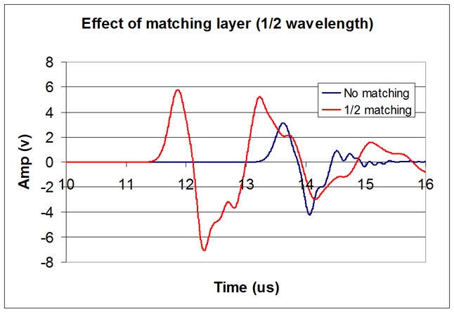
Effect of Matching Layer In transducer design, the piezoelectric layer typically is cut to 1/2 the desired wavelength. To get as much energy out of the transducer as possible, an impedance matching layer is usually placed on top of the active layer of the piezoelectric element. Optimal impedance matching is achieved by sizing the matching layer so that its thickness is nominally 1/4 of the desired wavelength. This design maintains waves that were reflected within the matching layer to be in phase when they exit the layer. For medical transducers, the matching layer is made of a material that has acoustical impedance between the active element and water (nominally equal to the square root of the product of the acoustic impedances of piezoelectric element and the medium into which the ultrasound wave is to propagate, for example, soft tissue). The following two figures show the comparison between transducers without a matching layer, and with a 1/4 wavelength matching layer and with a 1/2 wavelength matching layer, respectively.
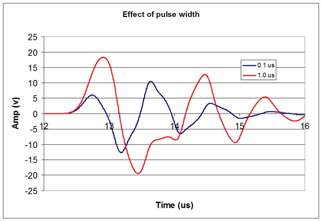
Effect of Pulse Width Besides backing and matching layers, input signal duration variations also will affect the shapes of the output signals. In all the above models, a 0.1 us pulse was applied to the source transducer. To investigator the effect of pulse duration, a model with 1 us pulse was simulated and compared to the results with a 0.1 us input pulse (see the following figure).
Tips for running the Wave2000 Plus models: (1) To increase the accuracy of the numerical solution, the user can choose a higher grid resolution. To change the resolution of a model, use menu command Wave->Job Parameters to set Point/Cycle. A bigger number means higher resolution. To ensure a model provides an accurate result, the user can try a couple of different resolutions. When the results do not change or change little after increasing resolution, the result can be considered as converged. (2) A model may become unstable after changing some parameters. In most cases, reducing the simulation time step can make an unstable model stable. To change the time step, use menu command Wave->Job Parameters, set the Time Step Scale. A smaller value means smaller time step. Generally, start from 1 and decrease Time Step Scale in small steps (1 to 0.9, 0.9 to 0.8; the largest value that maintains stability is the correct one to use, i.e., use 0.8 and not 0.7 if 0.8 works to maintain stability). (3) To display receiver potential (voltage) output, after running a model, use menu command Tools->Receiver Plot, then click on "Disable All" button, click on "Next" until "R-Potential (E)", uncheck "Disable" and click on "Apply". To save the receiver potential output to a file for later processing, before running a model, use menu command Wave->Electrode Configuration, click on "Next" until "R-Potential" name displays, click "Save to file" and choose a file to save, then click on "Apply", click on "OK" to close the dialog. (4) To change pulse width, use menu command Wave->Electrode Pair Configuration, select "Source", click on "Detail" for "A-Given Potential", set desired value and click on "OK", and then "Apply" and "OK" .
Go to Tutorial II
|
|||||||||

© 2024 CyberLogic, inc. All Rights Reserved